


| D2X2B Mechanical Fiber Optic Switch |

SYOPTEK designs and manufactures the most affordable high performance Mechanical Optical Switch. By state of art technologies, SYOPTEK optical switch is not affected by the polarization and wavelength, it offers ultra-high reliability, fast switching speed, low insertion loss, and bi-directional performance. Our optical switch products support, improve overall system cost to meet global demand of large bandwidth network.
Features
-Fast switching speed
-Unmatched Low Cost
-Low lnsertion Loss & PDL
-Latching or Non-Latching
-High Channel lsolation
-High stability and reliability
Applications
-Protection/Redundancy of fiber network
-Re-configurable Optical Add/Drop Multiplexing
-Optical Cross Connect (OXC)
-Channel Selectors
-Optical Spectral Monitoring (OSM)
-Optical Test Equipments
-Self station monitoring
-Epoxy-Free Optical Path
Performance:
Model |
D2*2B |
||
Operating wavelength |
nm |
850±40/1300±40 |
1260~1620 |
wavelength |
nm |
850&1300 |
1310&1550 |
Insertion loss |
dB |
Typ:1.0 Max:1.5 |
|
Return loss |
dB |
MM≥30 SM≥50 |
|
Cross talk |
dB |
MM≥35 SM≥55 |
|
PDL |
dB |
≤0.05 |
|
WDL |
dB |
≤0.25 |
|
TDL |
dB |
≤0.25 |
|
Repeatability |
dB |
≤±0.02 |
|
Voltage |
v |
3.0 or 5.0±0.5 |
|
Operating life |
Time |
≥107 |
|
Switch time |
ms |
≤8 |
|
Power handling |
mW |
≤500 |
|
Operating temperature |
℃ |
-20~+70 |
|
Storage temperature |
℃ |
-40~+85 |
|
Fiber color |
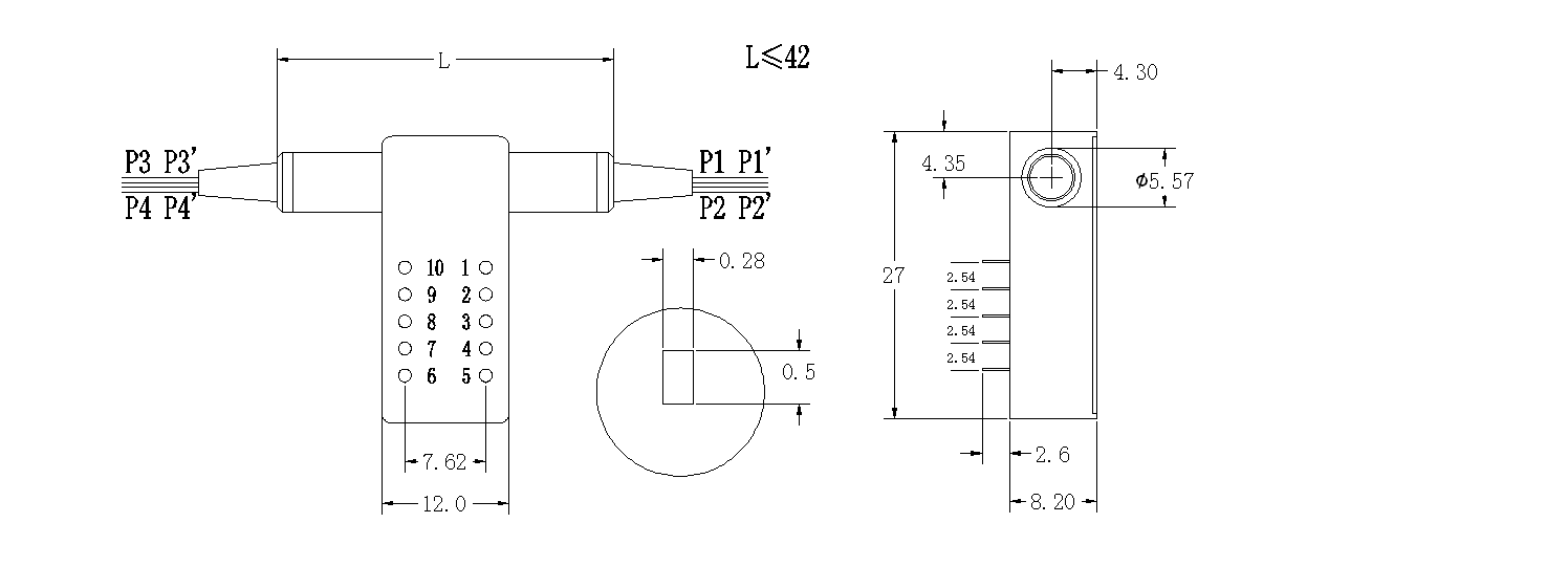
P1、P1’:White P2、P2’:Black P3、P3’:Red P4、P4’:Blue |
||
Size |
mm |
27.0×12×8.2±0.2 |
|
Note: 1. Within operating temperature and SOP. 2. Excluding Connectors.
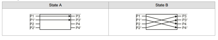
Pin Definition:
Type |
State |
Pin definition |
Power |
Condition monitoring |
||||||
D2x2 |
1 |
5 |
6 |
10 |
2-3 |
3-4 |
7-8 |
8-9 |
||
Non-latching |
A |
P1-P3 |
-- |
-- |
-- |
-- |
Close |
Open |
Open |
Close |
P1’-P3’ |
||||||||||
B |
P1-P4、P2-P3 |
V+ |
-- |
-- |
GND |
Open |
Close |
Close |
Open |
|
P1’-P4’、P2’-P3’ |
||||||||||
Latching |
A |
P1-P3 |
-- |
-- |
GND |
V+ |
Close |
Open |
Open |
Close |
P1’-P3’ |
||||||||||
B |
P1-P4、P2-P3 |
V+ |
-- |
GND |
-- |
Open |
Close |
Close |
Open |
|
P1’-P4’、P2’-P3’ |
||||||||||
Path Diagram:
Production Size:
Order Information:
XXXX— |
XX— |
XXXX |
|||
Wavelength |
Operating Voltage |
Fiber Type |
Tube Type |
Fiber Length |
Connector |
0850—850 1315—1310&1550 …… |
3L—3v, latching 5L—5v, latching 3N—3v, Non-latching 5N—5v, Non-latching |
1—SM 2—MM 62.5/125 3—MM 50/125 |
1—250um 2—900um |
00—Other 05—0.5m±5cm 10—1m±5cm 15—1.5m±5cm 20—2 m …… |
0—Other 1—FC/PC 2—FC/APC 3—SC/PC 4—SC/APC 5—LC/PC 6—LC/APC |


