Visual tracing
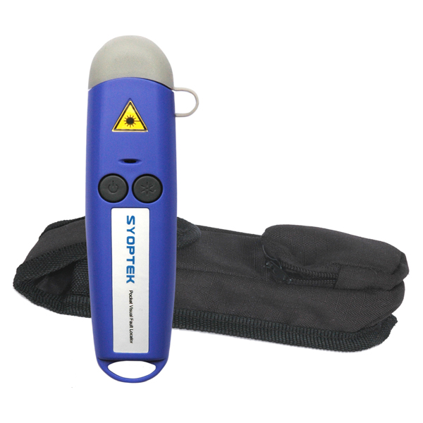 Continuity checking makes certain the fibres are not broken and to trace a path of a fibre from one end to another through many connections. Use a visible light “fibre optic tracer” or “pocket visual fault locator“. It looks like a flashlight or a pen-like instrument with a light bulb or LED source that mates to a fibre optic connector. Attach a cable to test to the visual tracer and look at the other end to see the light transmitted through the core of the fibre. If there is no light at the end, go back to intermediate connections to find the bad section of the cable.
A good example of how it can save time and money is testing fibre on a reel before you pull it to make sure it hasn’t been damaged during shipment. Look for visible signs of damage (like cracked or broken reels, kinks in the cable, etc). For testing, visual tracers help also identify the next fibre to be tested for loss with the test kit. When connecting cables at patch panels, use the visual tracer to make sure each connection is the right two fibres! To make certain the proper fibres are connected to the transmitter and receiver, use the visual tracer in place of the transmitter and your eye instead of the receiver (remember that fibre optic links work in the infrared so you can’t see anything anyway).
Visual fault location
A higher power version of the tracer uses a laser that can also find faults. The red laser light is powerful enough to show breaks in fibres or high loss connectors. You can actually see the loss of the bright red light even through many yellow or orange simplex cable jackets except black or grey jackets. You can also use this gadget to optimise mechanical splices or prepolished-splice type fibre optic connectors. In fact, don’t even think of doing one of those connectors without one; no other method will assure you of high yield with them.
Visual connector inspection
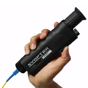
Fibre optic microscopes are used to inspect connectors to check the quality of the termination procedure and diagnose problems. A well made connector will have a smooth, polished, scratch-free finish and the fibre will not show any signs of cracks, chips or areas where the fibre is either protruding from the end of the ferrule or pulling back into it.
The magnification for viewing connectors can be 30 to 400 power but it is best to use a medium magnification. The best microscopes allow you to inspect the connector from several angles, either by tilting the connector or having angle illumination to get the best picture of what’s going on. Check to make sure the microscope has an easy-to-use adapter to attach the connectors of interest to the microscope.
And remember to check that no power is present in the cable before you look at it in a microscope – protect your eyes!