Archive for January 2016

Harsh environment fiber-optic components market hit $1.3 billion in 2015

passive optical components

According to the study, the value of passive optical components, led by fiber-optic cable assemblies (glass optical fiber/GOF plus plastic optical fiber/POF), in harsh environments reached $711 million in 2015. Transmitter/receiver units, held a 43% percent share of total components consumption in 2015. The total use of fiber-optic components used in all harsh environment applications is forecast to increase at an average annual growth rate of 14.6 % from $1.3 billion in 2015 to $2.6 billion in 2020.

The report notes that, historically, the market value of harsh environment fiber-optic components and devices has been dominated by military/aerospace-qualified components, with a 68% share in back in 2010. “However, we forecast that the military/aerospace application’s market share will decrease over the forecast period (2015-2020),” said the analyst, who added, “The commercial/industrial fiber-optic component consumption, in turn, is dominated by plastic optical fiber (POF) link components. However, glass-based optical fiber is finding an increase in opportunity in commercial/industrial applications.”

Harsh Environment (HE) is defined by the report as environment beyond the limits normally encountered by commercial telecom, datacom and commercial intra-equipment fiber data links with regard to extremes of: temperature above or below (-40 to +75) degrees C; shock and vibration; external pressure extremes; tensile strength of fiber; high EMI/RFI interference; corrosive and/or solvent surroundings; atomic and other radiation; and rough handling during installation/deployment.

How To Make A Perfect Fusion Splice?

fusion splicer

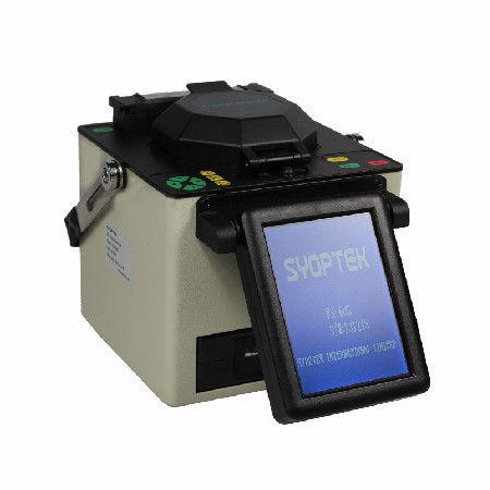
Fusion splice process is to literally weld two prepared fiber ends together, thereby creating a permanent joint with the minimum possible insertion loss. The fusion splice process is illustrated as follows.

Fusion Splice

So what factors in the fusion splice process determine the insertion loss achieved? The loss mechanism in fusion splice joint may be summarized as follows:

  • Core misalignment. Although normally aligned using the cladding diameter as the reference surface, it is generally believed that the complex surface tension and viscosity structures within the core and the cladding do tend to minimize the actual core misalignment.
  • Core diameter. The allowable diameter tolerances creates the possibility of attenuation within the joint.
    However, where differences between core diameters are large the welding of core to cladding inevitably takes place, which can either exaggerate or reduce the resultant losses. As a logical extension to this it should be obvious that optical fibers having different geometries are difficult if not impossible to joint using the fusion splice method.
  • Numerical aperture. The above comments regarding core diameter apply also to numerical aperture mismatches.

In addition to these losses, which are almost unavoidable, the level of skill involved in the process demands few abilities other than those necessary to prepare the fiber ends by cleaving. Nevertheless, poor levels of cleanliness and unacceptable cleaving of the ends will incur additional losses due to the inclusion of air bubbles or cracks. Incorrect equipment settings will also influence losses achieved and may result in incomplete fusion.

Fusion splicing is capable of producing the lowest loss joints within any optical fiber system, but their permanence limits their application. The need for demountable connections necessary to facilitate patching, repair and connection to terminal equipment forces the use of jointing techniques which use mechanical splices.

Ideal Networks offers online quote builder for cable test hardware packages

OTDRIdeal Networks recently unveiled an online Quote Builder that the company says “enables network cable installers to easily select a cable certifier package that meets their specific job requirements, helping to drive down purchase costs.”

Tim Widdershoven, global marketing manager for Ideal Networks, describes the Quote Builder as “an easy-to-use visual guide that enables cable installers to make an informed buying decision” while building a tailored fiber optic tester solution. Widdershoven continued, “Previously, cable certifiers have only been available in bundles, which may include extra components or functionality that a customer will simply never use. Using our new Quote Builder function online, customers can pick-and-mix from various options to find a certifier that meets their specific requirements and budget in six simple steps.”

Users of the Quote Builder begin by choosing either a 500-MHz Category 6A or 1000-MHz Category 7A certifier, then adding adapters. Permanent link adapters can be used for testing cabling from the outlet to the patch panel, or channel adapters can be used to certify the entire link—including patch cords. Next, users select any fiber modules required, to add Tier 1 fiber-optic cable certification. Following that, accessories are added, such as calibration cables, coaxial adapters, or an industrial Ethernet kit if required. Finally, users select a 1-, 2-, or 3-year CarePlan. Once the user enters some basic contact information, the user receives a quote.

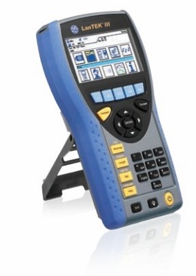
Ideal Networks further pointed out that one piece of fiber opitc test equipment users can specify via the Quote Builder is its LanTek III Cable Certifier (pictured). Introduced in December, the LanTek III is available in 500-MHz (Category 6A) and 1000-MHz (Category 7A) models. “For fiber cabling, the new FiberTek III modules can be added to the LanTek III-500 or LanTek III-1000 models to provide Tier 1 certification, eliminating the need for additional fiber testers,” Ideal Networks said.