Archive for Learning Center

The rules should be followed for cable plant hardware.

Various enclosures, cabinets, racks and panels are used to protect and organise splice and termination points. The network designer should know the type of network, support systems and the routes to be taken. Then the connection/splice locations can be determined and the hardware planned.

There are lots of rules to follow, of course (the EIA/TIA 569 has something to say about all this).

Here are some examples of fiber optic hardware:

  • Breakout kits – allow you to separate and protect individual fibres in a loose tube cable so it can be terminated
  • Splice enclosures – for long cable runs outside, the point where cables are spliced, sealed up and buried in the ground, put in a vault of some kind or hung off a pole
  • Splice panels – connect individual fibres from cables to pigtails
  • Patch panels – provides a centralised location for patching fibers, testing, monitoring and restoring cables
  • Racks and cabinets – enclosures for patch panels and splice panels. Usually these also include cable management – without this the cables start looking like spaghetti!

The rules should be remembered when you pulling fiber optic cable.

Installation methods for both wire cables and optical fiber cables are similar. fiber cable can be pulled with much greater force than copper wire if you pull it correctly. Just remember these rules:

1. Do not pull on the fibers, pull on the strength members only! The cable manufacturer gives you the perfect solution to pulling the cables, they install special strength members, usually duPont Kevlar aramid yarn or a fiberglass rod to pull on. Use it! Any other method may put stress on the fibers and harm them. Most cables cannot be pulled by the jacket. Do not pull on the jacket unless it is specifically approved by the cable manufacturers and you use an approved cable grip.

2. Do not exceed the maximum pulling load rating. On long runs, use proper lubricants and make sure they are compatible with the cable jacket. On really long runs, pull from the middle out to both ends. If possible, use an automated puller with tension control or at least a breakaway pulling eye.

3. Do not exceed the cable bend radius. fiber is stronger than steel when you pull it straight, but it breaks easily when bent too tightly. These will harm the fibers, maybe immediately, maybe not for a few years, but you will harm them and the cable must be removed and thrown away!

4. Do not twist the cable. Putting a twist in the cable can stress the fibers too. Always roll the cable off the spool instead of spinning it off the spool end. This will put a twist in the cable for every turn on the spool! If you are laying cable out for a long pull, use a “figure 8” on the ground to prevent twisting (the figure 8 puts a half twist in on one side of the 8 and takes it out on the other, preventing twists.) And always use a swivel pulling eye because pulling tension will cause twisting forces on the cable.

5. Check the length. Make sure the cable is long enough for the run. It’s not easy or cheap to splice fiber and it needs special protection. Try to make it in one pull, possible up to about 2-3 miles.

6. Conduit and Innerduct: Outside plant cables are either installed in conduit or innerduct or direct buried, depending on the cable type. Building cables can be installed directly, but you might consider putting them inside plenum-rated innerduct. This innerduct is bright orange and will provide a good way to identify fiber optic cable and protect it from damage, generally a result of someone cutting it by mistake! The innerduct can speed installation and maybe even cut costs. It can be installed quickly by unskilled labour, then the fiber cable can be pulled through in seconds. You can even get the innerduct with pulling tape already installed.

How to choose a right cable.

With so much choice in cables, it is hard to find the right one.

The table below summarises the choices, applications and advantages of each.

It will be helpful for you to choose a right one.

Cable type Application Advantages
Tight Buffer Premises Makes rugged patchcords
Distribution Premises Small size for lots of fibres, inexpensive
Breakout Premises Rugged, easy to terminate, no hardware needed
Loose Tube Outside Plant Rugged, gel or dry water-blocking
Armoured Outside Plant Prevents rodent damage
Ribbon Outside Plant Highest fibre count for small size

Do you really need different cable testing devices?

OTDRIt’s easy to be streaming a demo video in the middle of a teleconference with an important customer and NOT think about how this is actually happening. But if you are at all involved in structured cabling or network management, or share responsibility for these things from a facilities perspective, then you DO think about it. You know, for instance, that in recent years Ethernet speeds and bandwidth have increased by yet another order of magnitude. You also know higher speeds are the result of technological refinements that increase various interactions in the physical and data layers of a cable link over shorter periods of time in the same amount of space.

This complex interweave of materials, signal and math is the primary reason devices for testing LAN links have become so sophisticated. The sophistication comes in many forms—type and number of tests, speed, ergonomics, full color touch screen, document-based reporting—and causes devices to fall into a few basic categories. This is important because the cost associated with testing devices varies considerably with their purpose and their capabilities. This in turn suggests an overall strategy for cabling contractors to deploy multiple devices and helps both contractors and facilities managers avoid over- or under-spending in this area. More on that in a moment.

Cable and Network Testing

Let’s take a quick look at the breakdown of testing and devices. One of the simplest cable tests, called wire mapping, sends a signal down the link to see if anything is wrong, broken or missing.

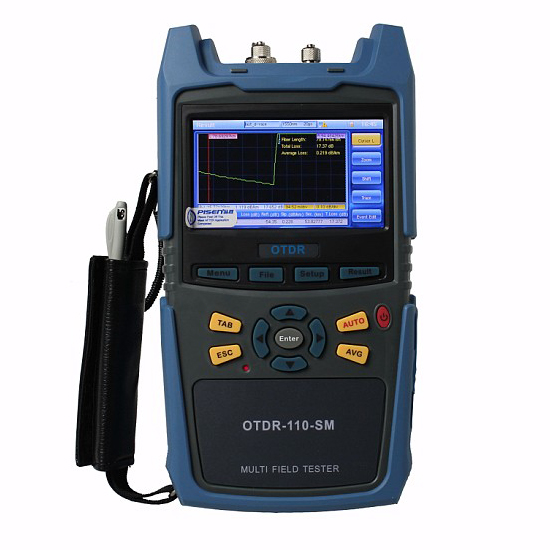
A method called time domain reflectometry measures the speed of the signal and maps the channel topology, precisely locating any of a number of possible faults. Sometimes called OTDR or verifiers, these simple wire mapping devices are the equivalent of a pocket knife and should be hanging from every technician’s belt.

A somewhat more useful foundational cable testing device will be able to detect Power over Ethernet (PoE) and capture any networked phones, cameras or other low-voltage devices in the wire map.

The next step up in verifiers enables the technician to troubleshoot the network by identifying specific faults in both the physical and link layers in a channel. What does this mean? Simply that, in addition to broken or split wires, bad connections or other issues associated with the signal itself, the tester will perform a network discovery that tests the data protocols at each link to make sure all devices on the network are properly identifying one another.

Whether you are installing a new run or troubleshooting a faulty one, someone is going to need to test both the physical and link layers and prove that the network is operating to specifications. That takes us to a considerably higher level of testing, typically called qualification or transmission testing. But before we go there, let’s skip to the top for a moment.
Cable Systems and Network Certification

New builds and component manufacturer warranties typically require cabled systems to be certified. Certification means a pass/fail judgment of network performance based on a battery of tests performed, recorded and reported within a very specific procedural framework set forth by applicable TIA and ISO/IEC standards. This goes beyond the ability to determine whether your network does what you and your customer want it to do. You are proving, guaranteeing, certifying to the rest of the world that your network meets the same standards applied to every other network of that type or class. Moreover, it is not you that is doing the certifying, but rather your sophisticated, impartial, and, yes, expensive testing device. And there it is: the certifying tester itself is a product of global telecommunications standards. To be useful, it must be able to measure specifications well beyond those standards in order to render results within comfortable margins and provide headroom for the future. That’s why, for example, the WireXpert certifier from Softing was designed years ago with a frequency range up to 2,500 MHz—far in excess of the Category 8 cabling standard, which has only just now been approved.
Network Link Qualification

As a practical matter, certification only happens after everything has already been installed, fixed and tested. That leaves a lot of situations short of certification where the testing and reporting capabilities of a certifier could come in handy. That is the space occupied by qualifiers.

Softing’s qualifier, called NetXpert, leans toward the same lab-grade testing technology in a battery-powered handheld device that engineers developed for the WireXpert. Basically, the NetXpert qualifier does all the troubleshooting of cable/network testers with one very important addition: It can verify Gigabit Ethernet operation compliant with the IEEE 802.3ab standard. It does this through bit error rate test (BERT), a form of data transmission testing that sends 10 million bits in 10 seconds (1 Gbit/sec), counts the errors, then issues a PASS/FAIL. While distinct from certification, a BERT pass essentially proves the speed of a cable channel is up to standard.

In this way, LAN links are qualified as part of the installation, troubleshooting and repair procedure. You could think of a qualification pass as a sort of precertification that means whatever you are testing is working up to standards and you can move on. At less than a third of the cost of certifiers, it makes sense for every cabling crew to pack a network qualifier. On the other hand, at about twice the cost of a cable verifier it’s overkill to have everyone using them for routine wire mapping and troubleshooting.
Deploying Testing Devices

One way to understand the hierarchy among testing devices is to consider their deployment. Every cabling contractor location should have at least one certifier under a service contract plus one backup. Every crew needs to have a qualifier available to test the fix. Every technician should be carrying a cable verifier, whether they are part of a cabling contractor crew or a facilities management team.

Typically, cabling contractors will install, repair LANs for organizations even where there is an extensive facilities maintenance presence. But considering the high-performance nature of 10G+ Ethernet, it makes sense for in-house staff to be equipped to perform at least some of the initial wire mapping and troubleshooting activities. Where appropriate, cabling contractors should consider putting foundational tools like cable and network verifiers in their customers’ hands as part of a job or service agreement. It’s a good way to help customers retain control, save money and experience less network problem time. It also makes the contractor’s time and resources on service calls more efficient while giving their customers one less reason to do business with a competitor.

In addition to the WireXpert CAT-8 certifier and the NetXpert qualifier, Softing now offers the CableMaster line of cable and network verifiers to the North American market. (The CableMaster 800 is pictured above.) Don’t overspend and under deploy. Make sure you’re using the right testing device for the right job and that everyone on your team—including your customers—has what they need, when they need it.

What’s the cable design criteria ?

When you design the cable, you should know the following criteria.

1. Pulling strength

Some cable is simply laid into cable trays or ditches, so pull strength is not too important. But other cable may be pulled thorough 2 km or more of conduit. Even with lots of cable lubricant, pulling tension can be high. Most cables get their strength from an aramid fiber (Kevlar is the duPont trade name), a unique polymer fiber that is very strong but does not stretch – so pulling on it will not stress the other components in the cable. The simplest simplex cable has a pull strength of 100-200 pounds, while outside plant cable may have a specification of over 800 pounds.

2.Water protection

Outdoors, every cable must be protected from water or moisture. It starts with a moisture resistant jacket, usually PE (polyethylene), and a filling of water-blocking material. The usual way is to flood the cable with a water-blocking gel. It’s effective but messy – requiring a gel remover (use the commercial stuff – it’s best- -but bottled lemon juice works in a pinch!). A newer alternative is dry water blocking using a miracle powder – the stuff developed to absorb moisture in disposable diapers. Check with your cable supplier to see if they offer it.

3. Fire code ratings

Every cable installed indoors must meet fire codes. That means the jacket must be rated for fire resistance, with ratings for general use, riser (a vertical cable feeds flames more than horizontal) and plenum (for installation in air-handling areas. Most indoor cables us PVC (polyvinyl chloride) jacketing for fire retardance. In the United States, all premises cables must carry identification and flammability ratings per the NEC (National Electrical Code) paragraph 770. These ratings are:

NEC Rating Description
OFN Optical fiber Non-conductive
OFC Optical fiber Conductive
OFNG or OFCG General purpose
OFNR or OFCR Riser rated cable for vertical runs
OFNP or OFCP Plenum rated cables for use in air-handling plenums
OFN-LS Low smoke density

Cables without markings should never be installed as they will not pass inspections! Outdoor cables are not fire-rated and can only be used up to 50 feet indoors. If you need to bring an outdoor cable indoors, consider a double-jacketed cable with PE jacket over a PVC UL-rated indoor jacket. Simply remove the outdoor jacket when you come indoors and you will not have to terminate at the entry point. You can use an Indoor/Outdoor rated product with a Low Smoke Zero Halogen jacket.

The cable types you should know.

The cable include the following types, it’s important for you to choose suitable one.

Simplex and zip cord

Simplex cable is one fiber, tight-buffered (coated with a 900 micron buffer over the primary buffer coating) with Kevlar (aramid yarn) strength members and jacketed for indoor use. The jacket is usually 3mm (1/8 in.) diameter. Zipcord is simply two of these joined with a thin web. It’s used mostly for patch cord and backplane applications, but zipcord can also be used for desktop connections.

Distribution cable

This contains several tight-buffered fibers bundled under the same jacket with Kevlar strength members and sometimes fiberglass rod reinforcement to stiffen the cable and prevent kinking. The cable is small in size, and used for short, dry conduit runs, riser and plenum applications. The fibers are double buffered and can be directly terminated, but because their fibers are not individually reinforced, these cables need to be broken out with a “breakout box” or terminated inside a patch panel or junction box.
Breakout cable

This cable is made of several simplex cables bundled together. This is a strong, rugged design, but is larger and more expensive than the distribution cables. It is suitable for conduit runs, riser and plenum applications. Because each fiber is individually reinforced, this design allows for quick termination to connectors and does not require patch panels or boxes. Breakout cable can be more economic where fiber count isn’t too large and distances too long, because is requires so much less labour to terminate.
Loose tube cable

This cable is composed of several fibers together inside a small polymeric buffer tube or tubes, which are in turn wound around a central strength member and jacketed, providing a small, high fiber count cable. This type of cable is ideal for outside plant trunking applications, as it can be made with the loose tubes filled with gel or water absorbent powder to prevent harm to the fibers from water. It can be used in conduits, strung overhead or buried directly into the ground. Since the fibers have only a thin buffer coating, they must be carefully handled and protected to prevent damage.
Ribbon cable

This cable offers the highest packing density, since all the fibers are laid out in rows, typically of 12 fibers, and laid on top of each other. This way 144 fibers only has a cross section of about 1/4 inch or 6 mm! Some cable designs use a “slotted core” with up to 6 of these 144 fiber ribbon assemblies for 864 fibers in one cable! Since it’s outside plant cable, it’s gel-filled for water blocking.
Armoured cable

Cable installed by direct burial in areas where rodents are a problem usually has metal armouring between two jackets to prevent rodent penetration. This means the cable is conductive, so it must be grounded properly.

Aerial cable

Aerial cable is for outside installation on poles. It can be lashed to a messenger or another cable (common in CATV) or have metal or aramid strength members to make it self-supporting.

Fiber Optics Proving a Valuable Investment for the Data Center

Fiber-optic connectivity is on the rise in the data center as cloud uptake grows and a services-based technology climate becomes pervasive. Service providers are looking for ways to simplify deployment and delivery of new services and fiber optics offer a fast and efficient way to handle the onslaught of traffic and services.

According to ACG Research, the global market for optical data center interconnect (DCI) technology is set to reach $4.7 billion by 2019, growing at an accelerated 44.9 percent CAGR from 2014. Fueled by new and expanded data center deployments along with the need to automate and virtualize a host of functions, high-speed optical DCI connections meet demands for increased capacity, better resiliency and versatility.

Fiber-optic modules and cable types are also evolving to meet the unique needs of the data center. While the SFP module format is a standard for 1 GbE, the SPF+ module has evolved to support speeds up to 10 GbE, in the same small form factor as the original SFP module. And many switches support both SFP and SFP+, offering scalability and flexibility for data center operators.

Most fiber optic cables now include digital diagnostic monitoring or digital optical monitoring, which provide information about the optics to the platform the cable is connected to. Switches pull critical information like receive light level, transmit power and transceiver temperature in real time and report it to data center administrators. This enables quick and easy troubleshooting for a variety of optical link issues while also ensuring the cable and transceiver are operating up to capacity.

Two major data center fiber-optic announcements within the past week signify the massive uptake within the data center sector. U.K.-based cloud and hosting provider BSO announced a fiber-optic network between the New York City financial district and Chicago’s financial district, connecting several Equinix data centers along the way. Amazon is also exploring the best route for a planned fiber-optic cable system across the Pacific Ocean, which will connect data centers in the US, Australia and New Zealand. The cable is expected to go live in 2018.

SYOPTEK’S One-Click Cleaner MU/LC (Cleans LC,MU connectors)

one click cleaner lc
SYOPTEK’S One-Click Cleaner LC is an easy-to-use option for cleaning connectors in adapters. Simply insert the One-Click Cleaner into an

adapter and push until an audible “click” is heard. The One-Click Cleaner uses the mechanical push action to advance an optical grade

cleaning tape while the cleaning tip is rotated to ensure the fiber end-face is effectively, but gently, cleaned.

The One-Click Cleaner  is a must-have for field technicians. Small enough to fit in a shirt pocket and a great addition to cleaning kits.

Save your wrist – no more twist!
Read more

Why Category 6A Should Be Your Cable of Choice.

6a

“More businesses are turning to Category 6A cabling for their network infrastructure,” notes the company. “This decision is primarily being driven by affordable price, high quality, and exceptional performance. THe followings are five reasons why you should choose Category 6A cable for your enterprise applications”:

1. Category 6A supports all data rates up to and including 10GBASE-T.  

Category 6A ensures that your installation will be prepared to run all data rates up to and including 10 gigabits per second. Businesses today rely on data-heavy applications like video, wireless, and desktop virtualization, so it’s critical to have a network infrastructure that will support these and future applications.

2. Speeds like 10GBASE-T will soon become common.

It’s expected that common low-cost, mass-market switches will require Category 6A cable before the end of 2016. This is reinforced by industry forecasts that predict 10GBASE-T will soon be the norm.

3. Wireless access point speeds are accelerating.

The growing demands of mobile devices are driving the need for greater bandwidth. Today’s high-end wireless access points can operate around 1.2 to 2.6 Gbps. Seven Gbps WAPs are expected by 2017, and they’ll require 10GBASE-T. Category 6A cabling infrastructure has the capacity to meet these needs.

4. There are no bundle limits for applications like HDBaseT or higher Power over Ethernet (PoE++).

HDBaseT places bundle limitations on Category 5e and 6 due to alien crosstalk. Because Category 6A is designed to suppress alien crosstalk, there are no limitations on bundling with Category 6A. Category 6A cables are also much better at dissipating heat. This makes them perfect to manage the upcoming 802.3bt PoE++ standards since they deliver both 49W and 96W of power to end devices. Due to the higher 96W power running on multiple cables in a bundle, Category 5e and 6 bundle sizes will be limited – Category 6A cables will not be.

5. 10GBASE-T is the low-cost 10 gigabit option.

When comparing prices per gigabit, 10GBASE-T provides a much lower total cost of ownership versus 1000BASE-T. This is driven by increasing switch volumes (which are driving down prices) and the introduction of more LAN on Motherboard (LOM) servers with “free” RJ45 connectivity.

The 5 most damaging structured cabling scenarios.

HNM-25

why such problems need to be addressed sooner rather than later? The following Cause-and-Effect checklist of the 5 most damaging structured cabling scenarios give a short explanations to illustrate them.

1.  Cause:  Intermittent faults – Unidentified intermittent faults are amongst the most common and damaging issues that affect structured cabling networks. Faulty patch leads and broken or malfunctioning outlets are typical causes of this frustrating and puzzling problem, but identifying the lead or outlet that’s misfiring can be a headache in itself.

Effect:  Valuable resources are wasted.

2. Cause: Wi-Fi problems – Wi-Fi can present a host of challenges when installed incorrectly – from poor coverage to intermittent connectivity. Connecting multiple devices that use conflicting Wi-Fi standards is a common cause of many problems. Equally, the Wi-Fi devices themselves may be faulty or installed in the wrong position. If neither of these factors are the cause of your issues, check if you’ve connected new Wi-Fi devices with outdated cabling.

Effect:  Workforce efficiency and productivity plummet.

3. Cause: Disorganization and disorder – Structured cabling networks often become disorderly over time as multiple firms are called in to install cable, maintain and repair them, resulting in a confused and jumbled system. A disorganized structured cabling network can also be the result of sloppy workmanship, where engineers haven’t taken enough care during the implementation process. Untidy patching, inaccurate labelling and poor record keeping are all warning signs that shouldn’t be ignored.

Effect:  Unnecessary expenditure.

4. Cause: Mismatched cabling –  Even if your infrastructure is built on one category of cable, if two different manufacturers have supplied different elements of your network, you may encounter problems. A structured cabling network that isn’t consistent end-to-end can cause electrical mismatching between components and although this can be difficult to spot, the effects are plain to see.

Effect:  Costly network challenges.

5.  Cause: A lack of network redundancy – Organizations need a backup cabling network and an uninterruptable power supply (UPS) to ensure connectivity and power remain consistent when the lights go out unexpectedly. This is especially true of critical links and services that underpin crucial business operations, for example the structured cabling network that supports a bank’s trading floor. Despite the importance of these systems, we find that many organizations don’t consider installing them until after an incident has taken place.

Effect: A catastrophic loss of service.