Archive for May 2014

Fiber optic installation best practices start with inspection

For centuries, optics have been inspected and cleaned to ensure the proper passage of light, and the advent of fiber optic cabling systems has resulted in yet another application where care and cleanliness are important. While fiber connector inspection and cleaning are not new, they are growing in importance as links are pushed to carry higher data rates, driving decreasingly small loss budgets.

Fiber optic cabling carries pulses of light between transmitters and receivers. These pulses represent data being sent across the cable. For data to be transmitted successfully, the light must arrive at the far end of the cable with enough power to be measured.

Among key sources of loss that can bring a fiber network down, dirty and damaged end-faces are perhaps the most underestimated. In one survey, dirty end-faces were found to be the No.1 cause of fiber link failure for both installers and private network owners; contaminated end-faces were the cause of fiber links failing 85% of the time.

Sources of fiber optic light loss

Two types of problems cause loss as light leaves one end-face and enters another inside an adapter: contamination and damage:

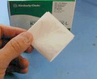
Contamination comes in many forms, from dust and oils to buffer gel. Simply touching the ferrule will immediately deposit an unacceptable amount of body oil on the end-face.

Dust and small statically charged particles float through the air and can land on any exposed termination. This can be especially true in facilities undergoing construction or renovation. In new installations, buffer gel and pulling lube can easily find its way onto an end-face.

Damage will appear as scratches, pits, cracks or chips. These end-face surface defects could be the result of poor termination or mated contamination. Up to 5% of the outer edge of fiber cladding generally may be chipped as this is a common result of the polishing process. Any chips on the core are unacceptable.

In every instance, all end-faces should always be inspected before insertion. When a connector is being mated to a port, then the port should be inspected as well. Inspecting one side of a connection is ineffective as contamination inside a port may not only cause damage but also migrate to the connector being inserted. Equipment ports are frequently overlooked: not only as being contaminated themselves but as a source of contamination for test cords.

End-face inspection with a fiber microscope

Microscopes can be divided into two basic groupings:

Sometimes referred to as ‘patch cord scopes’, optical microscopes incorporate an objective lens and an eyepiece lens to allow you to view the end-face directly through the device. Today, the barrel-shaped microscopes are ubiquitous in termination kits and used to inspect patch cords during troubleshooting. The best feature of these microscopes is their price, as they are the least expensive way to see end-face details. Their drawback is that they are unable to view end-faces through bulkheads or inside equipment.

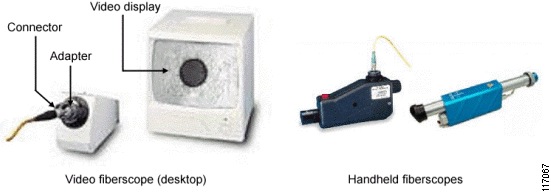
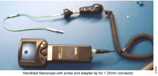
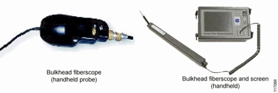
Video microscopes incorporate both an optical probe and a display for viewing the probe’s image. Probes are designed to be small so they can reach ports in hard-to-access places. The screens allow images to be expanded for better identifying contaminants and damage. Because the end-face is viewed on a screen instead of directly, probes eliminate any chance of harmful laser light reaching a person’s eye.
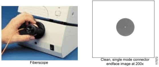
In fiber optic inspection, the goal is to identify all contaminants and damage of a minimum size and within a critical area. Users must first identify the appropriate minimum-sized contaminant or defect that will affect their system. Next, look for the microscope that has the largest field of view while maintaining the necessary detection capability (the smallest-sized item that a microscope can detect). It is preferable to see as much of the surface area as possible while maintaining requisite detection capability.

Best practices

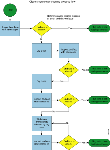
Fiber optic inspection must occur not only before but after cleaning to ensure a good result. When a post-cleaning inspection shows more contamination, then a another cleaning must follow. Second, both sides of any connection need to be inspected as every mating involves two surfaces coming into contact. Lastly, it is almost always easier and cheaper to inspect and clean as a preventive measure than as reactive response. Consistent inspection and cleaning upfront will avoid unexpected and costly downtime in the future.

visit http://www.fiberoptictesterdepot.com and check out our incredible inventory of fiber optic inspection equipment supplies; BEST PRICE, GREAT SERVICE.

Inspection and Cleaning Procedures for Fiber-Optic Connections CISCO(3)

Cleaning Techniques for Pigtails and Patch Cords

This section describes cleaning techniques for pigtails and patchcords.

Note: No known cleaning methods are 100% effective; therefore, it is imperative that inspection is included as part of the cleaning process. Improper cleaning can cause damage to the equipment.

Dry Cleaning Technique: Cartridge and Pocket Style Cleaners

This section describes dry cleaning techniques with the use of cartridge and pocket style cleaners.

Tools

117073.gif

caution Caution: Read the reminders and warnings before you begin this process.

  1. Make sure that the lasers are turned off before you begin the inspection.

    warning Warning: Invisible laser radiation might be emitted from disconnected fibers or connectors. Do not stare into beams or view directly with optical instruments.

  2. Remove the protective endcap and store it in a small resealable container.

  3. Inspect the connector with a fiberscope. See the Connector Inspection Technique section.

  4. If the connector is dirty, clean with a cartridge or pocket cleaner.

    • For cartridge cleaners, press down and hold the thumb lever. The shutter slides back and exposes a new cleaning area, then go to step 5.

    • For pocket cleaners, peel back protective film for one cleaning surface, and then go to step 5.

    • For manual advance cleaners, pull on the cleaning material from the bottom of the device until a new strip appears in the cleaning window, and then go to step 5.

  5. Hold the fiber tip lightly against the cleaning area.

    • For single, non-APC fiber connectors, rotate the fiber once through a quarter turn, 90 degrees.

    • For APC connector endfaces, hold cleaning area at the same angle as the endface.

  6. Pull the fiber tip lightly down the exposed cleaning area in the direction of the arrow or from top to bottom.

    caution Caution: Do not scrub the fiber against the fabric or clean over the same surface more than once. This can potentially contaminate or damage your connector.

    • For pocket style cleaners, go to step 8.

    • For single fiber connectors with the type A CLETOP, repeat the cleaning process in the second clean slot (step 5 and step 6).

  7. Release the thumb lever to close the cleaning window, if you use cartridge type cleaners.

  8. Inspect the connector again with the fiberscope. Refer to the Connector Inspection Technique section.

  9. Repeat the inspection and cleaning processes, as necessary.

    caution Caution: Throw away any used cleaning material, either cards or material cartridges, after use.

Dry Clean Technique: Lint-Free Wipes

This section describes dry cleaning techniques that use lint-free wipes.

Tools

  • Lint-free wipes, preferably clean room quality

Figure 8

95147.gif

caution Caution: Read the reminders and warnings before you begin this process.

  1. Make sure that the lasers are turned off before you begin the inspection.

    warning Warning: Invisible laser radiation might be emitted from disconnected fibers or connectors. Do not stare into beams or view directly with optical instruments.

  2. Remove the protective endcap and store it in a small resealable container.

  3. Fold the wipe into a square about 4 to 8 layers thick, see Figure 8.

  4. Inspect the connector with a fiberscope. Refer to the Connector Inspection Technique section.

    If the connector is dirty, clean it with a lint-free wipe.

    caution Caution: Be careful not to contaminate the cleaning area of the wipe with your hands or on a surface during folding.

  5. Lightly wipe the ferrule tip in the central portion of the wipe with a figure 8 motion.

    caution Caution: Do not scrub the fiber against the wipe. If you do it, it can cause scratches and more contamination.

  6. Repeat the figure 8 wiping action on another clean section of the wipe.

  7. Properly dispose of the wipe.

  8. Inspect the connector again with the fiberscope.

  9. Repeat this process as necessary.

Dry Clean: Lint-Free Swabs

This section describes dry cleaning techniques that uses lint-free swabs.

Tools

  • Lint-free swabs, preferably clean room quality

Figure 9

117074.gif

caution Caution: Read the reminders and warnings before you begin this process.

  1. Make sure that the lasers are turned off before you begin the inspection.

    warning Warning: Invisible laser radiation might be emitted from disconnected fibers or connectors. Do not stare into beams or view directly with optical instruments.

  2. Remove the protective endcap and store it in a small resealable container.

  3. Inspect the connector with a fiberscope. Refer to the Connector Inspection Technique section.

  4. If the connector is dirty, clean it with a lint-free swab.

    Figure 10

    95146.gif

  5. Lightly press and turn the swab to clean the ferrule face.

  6. Properly dispose of the swab. Never reuse a swab.

  7. Inspect the connector again with the fiberscope.

  8. Repeat this process as necessary.

Wet Cleaning Technique: Lint-Free Wipes

If a dry cleaning procedure does not remove the dirt from the fiber endface, then try the wet cleaning method.

caution Caution: Improper cleaning can cause damage to the equipment. The primary concern with the use of isopropyl alcohol is that it can be removed completely from the connector or adapter. Residual liquid alcohol acts as a transport mechanism for loose dirt on the endface. If the alcohol is allowed to evaporate slowly off the ferrule, it can leave residual material on the cladding and fiber core. This is extremely difficult to clean off without another wet cleaning and usually more difficult to remove than the original contaminant. Liquid alcohol can also remain in small crevices or cavities where it can re-emerge during fiber connection.

Tools

  • 99% isopropyl alcohol

  • Lint-free wipes

Figure 11

95147.gif

caution Caution: On female multifiber connectors, ensure that no alcohol gets into the guide pin holes. The alcohol might come out during mating and contaminate your connection.

caution Caution: Do not use wet cleaning on E-2000 or F-3000 connectors because the connector can trap the alcohol and re-contaminate the connector.

caution Caution: Read the reminders and warnings before you begin this process.

  1. Make sure that the lasers are turned off before you begin the inspection.

    warning Warning: Invisible laser radiation might be emitted from disconnected fibers or connectors. Do not stare into beams or view directly with optical instruments.

  2. Remove the protective endcap and store it in a small resealable container.

  3. Inspect the connector with a fiberscope. Refer to the Connector Inspection Technique section.

  4. Fold the wipe into a square, about 4 to 8 layers thick. See Figure 11.

  5. Moisten one section of the wipe with one drop of 99% alcohol. Be sure that a portion of the wipe remains dry.

  6. Lightly wipe the ferrule tip in the alcohol moistened portion of the wipe with a figure 8 motion. Immediately repeat the figure 8 wiping action on the dry section of wipe to remove any residual alcohol. (See Caution).

    caution Caution: Do not scrub the fiber against the wipe, doing so can cause scratches.

  7. Properly dispose of the wipe. Never reuse a wipe.

  8. Inspect the connector again with a fiberscope.

  9. Repeat the process as necessary.


Fiberopticcleanings.com stocks a variety of fiber optic cleaning supplies, from one click cleaners to NEOCLEAN-N optical connetor cleaner, from fiber optic cleaning wipes to fiber optic cleaning kit – everything you need for fiber optic cleaning jobs, BUY NOW and get FREE SHIPPING on most items!

400G first for submarine cable

Tata Communications, Huawei, and Huawei Marine have announced the successful completion of a 400G field trial on a subsea network over 6,000 km. The test results demonstrated an optical transmission of 400G signals, an industry-first for a submarine cable system of this length. 

Huawei and Huawei Marine say their technical solution ‘adopted the modulation format of dual carrier polarisation division multiplexing quadrature phase shift keying (DC-PDM-QPSK), an innovative ‘Faster-Than-Nyquist’ (FTN) compensation and recovery algorithm, proprietary clock recovery technology and soft decision forward error correction (SD-FEC) technology to address the problems of high-speed signal distortion and unstable clocks’. The use of such advanced technology underpins Huawei and Huawei Marine’s significant commitment to investing in research and development to meet the needs of their customers, the companies say.

Hon Kit Lam, vice president for international transmission and IP business at Tata Communications, said: ‘The 400G technology of Huawei & Huawei Marine demonstrates that our existing subsea network asset is capable of supporting future, next-generation transmission technology as shown in the 400G trial. Tata Communications constantly assesses new technology to expand our capabilities and to enhance our ability to support traffic growth demand from our customers.’

Jack Wang, president of Huawei Transmission Network Product Line, added: ‘Huawei has always taken a customer-centric approach to our research and development efforts. Our 400G technology will not only help operators manage larger levels of traffic faster, but also optimise operating and network maintenance costs. We are pleased to be working with leading international carriers like Tata Communications on this 400G technology trial.’

Fiber Optic Splicing Guide

What is Fiber Optic Splicing

Knowledge of fiber optic splicing methods is vital to any company or fiber optic technician involved in Telecommunications or LAN and networking projects.

Simply put, fiber optic splicing involves joining two fiber optic cables together. The other, more common, method of joining fibers is called termination or connectorization. Fiber splicing typically results in lower light loss and back reflection than termination making it the preferred method when the cable runs are too long for a single length of fiber or when joining two different types of cable together, such as a 48-fiber cable to four 12-fiber cables. Splicing is also used to restore fiber optic cables when a buried cable is accidentally severed.

There are two methods of fiber optic splicing, fusion splicing & mechanical splicing. If you are just beginning to splice fiber, you might want to look at your long-term goals in this field in order to chose which technique best fits your economic and performance objectives.

Mechanical Splicing vs. Fusion Splicing

Mechanical Splicing:
Mechanical splices are simply alignment devices, designed to
hold the two fiber ends in a precisely aligned position thus enabling light to pass from one fiber into the other. (Typical loss: 0.3 dB)

Fusion Splicing:
In fusion splicing a machine is used to precisely align the two fiber ends then the glass ends are “fused” or “welded” together using some type of heat or electric arc. This produces a continuous connection between the fibers enabling very low loss light transmission. (Typical loss: 0.1 dB)

• Which method is better?
The typical reason for choosing one method over the other is economics. Mechanical splicing has a low initial investment ($1,000 – $2,000) but costs more per splice ($12-$40 each). While the cost per splice for fusion splicing is lower ($0.50 – $1.50 each), the initial investment is much higher ($15,000 – $50,000 depending on the accuracy and features of the fusion splicing machine being purchased). The more precise you need the alignment (better alignment results in lower loss) the more you pay for the machine.

As for the performance of each splicing method, the decision is often based on what industry you are working in. Fusion splicing produces lower loss and less back reflection than mechanical splicing because the resulting fusion splice points are almost seamless. Fusion splices are used primarily with single mode fiber where as Mechanical splices work with both single and multi mode fiber.

Many Telecommunications and CATV companies invest in fusion splicing for their long haul singlemode networks, but will still use mechanical splicing for shorter, local cable runs. Since analog video signals require minimal reflection for optimal performance, fusion splicing is preferred for this application as well. The LAN industry has the choice of either method, as signal loss and reflection are minor concerns for most LAN applications.

Fusion Splicing Method
As mentioned previously, fusion splicing is a junction of two or more optical fibers that have been permanently affixed by welding them together by an electronic arc.

Four basic steps to completing a proper fusion splice:

Step 1: Preparing the fiber – Strip the protective coatings, jackets, tubes, strength members, etc. leaving only the bare fiber showing. The main concern here is cleanliness.

Step 2: Cleave the fiber – Using a good fiber cleaver here is essential to a successful fusion splice. The cleaved end must be mirror-smooth and perpendicular to the fiber axis to obtain a proper splice. NOTE: The cleaver does not cut the fiber! It merely nicks the fiber and then pulls or flexes it to cause a clean break. The goal is to produce a cleaved end that is as perfectly perpendicular as possible. That is why a good cleaver for fusion splicing can often cost $1,000 to $3,000. These cleavers can consistently produce a cleave angle of 0.5 degree or less.

Step 3: Fuse the fiber – There are two steps within this step, alignment and heating. Alignment can be manual or automatic depending on what equipment you have. The higher priced equipment you use, the more accurate the alignment becomes. Once properly aligned the fusion splicer unit then uses an electrical arc to melt the fibers, permanently welding the two fiber ends together.

Step 4: Protect the fiber – Protecting the fiber from bending and tensile forces will ensure the splice not break during normal handling. A typical fusion splice has a tensile strength between 0.5 and 1.5 lbs and will not break during normal handling but it still requires protection from excessive bending and pulling forces. Using heat shrink tubing, silicone gel and/or mechanical crimp protectors will keep the splice protected from outside elements and breakage.

Mechanical Splicing Method
Mechanical splicing is an optical junction where the fibers are precisely aligned and held in place by a self-contained assembly, not a permanent bond. This method aligns the two fiber ends to a common centerline, aligning their cores so the light can pass from one fiber to another.

Four steps to performing a mechanical splice:

Step 1: Preparing the fiber – Strip the protective coatings, jackets, tubes, strength members, etc. leaving only the bare fiber showing. The main concern here is cleanliness.

Step 2: Cleave the fiber – The process is identical to the cleaving for fusion splicing but the cleave precision is not as critical.

Step 3: Mechanically join the fibers – There is no heat used in this method. Simply position the fiber ends together inside the mechanical splice unit. The index matching gel inside the mechanical splice apparatus will help couple the light from one fiber end to the other. Older apparatus will have an epoxy rather than the index matching gel holding the cores together.

Step 4: Protect the fiber – the completed mechanical splice provides its own protection for the splice.

Tips for Better Splices:

1. Thoroughly and frequently clean your splicing tools. When working with fiber, keep in mind that particles not visible to the naked eye could cause tremendous problems when working with fiber optics. “Excessive” cleaning of your fiber and tools will save you time and money down the road.

2. Properly maintain and operate your cleaver. The cleaver is your most valuable tool in fiber splicing. Within mechanical splicing you need the proper angle to insure proper end faces or too much light escaping into the air gaps between the two fibers will occur. The index matching gel will eliminate most of the light escape but cannot overcome a low quality cleave. You should expect to spend around $200 to $1,000 for a good quality cleaver suitable for mechanical splicing.

For Fusion splicing, you need an even more precise cleaver to achieve the exceptional low loss (0.05 dB and less). If you have a poor cleave the fiber ends might not melt together properly causing light loss and high reflection problems. Expect to pay $1,000 to $4,000 for a good cleaver to handle the precision required for fusion splicing. Maintaining your cleaver by following manufacturer instructions for cleaning as well as using the tool properly will provide you with a long lasting piece of equipment and ensuring the job is done right the first time.

3. Fusion parameters must be adjusted minimally and methodically (fusion splicing only). If you start changing the fusion parameters on the splicer as soon as there is a hint of a problem you might lose your desired setting. Dirty equipment should be your first check and them continue with the parameters. Fusion time and fusion current are the two key factors for splicing. Different variables of these two factors can produce the same splice results. High time and low current result in the same outcome as high current and low time. Make sure to change one variable at a time and keep checking until you have found the right fusion parameters for your fiber type.

FiberOpticTools.net stocks a variety of fiber optic tools and fiber optic tool kit for your fiber optic splicing applications, BUY NOW and get FREE SHIPPING on most items!


Adtran drives FTTH network installation in rural Kansas

Blue Valley Tele-Communications (BVTC) is reportedly upgrading its fiber-optic network in 17 communities in northeastern Kansas via equipment from Adtran. The fiber-to-the-home (FTTH) deployment will secure the economic future of nearly 7500 residential and business customers in the area, the equipment provider asserts. “NEOCLEAN As an early adopter of fiber-optic networks, BVTC has always understood how technology can enable for rural communities the same innovation, growth, and prosperity found in larger metropolitan areas,” said a representative for Adtran.

“Not only are businesses in northeastern Kansas driving commerce growth via BVTC’s voice, video, and data services, but local schools are participating in distance learning,” added the company spokesperson. “The community is also benefiting from stronger medical care, as doctors are now able to consult and share digitally transmitted medical data with colleagues around the world from the local hospitals.”

In this most recent fiber-optic network upgrade, BVTC replaced its existing equipment (apparently from Tellabs) with Adtran’s integrated Total Access 5000 platform with Optical Networking Edge (ONE) capabilities to support the delivery of gigabit FTTH and Carrier Ethernet services through its access infrastructure, as well as leverage packet-optical transport to carry those premium services across its footprint. BVTC says it can now support stringent cloud and mobile backhaul service-level agreements as well as deliver IPTV, Ideal 45-163 voice over IP (VoIP), and high-speed Internet.
“Blue Valley Tele-Communications has always believed in the impact technology can have on the economic progress and quality of life for our customers. It truly has the ability to keep our communities on an even playing field with national and even global competitors,” says Jon Novak, project manager, Blue Valley Tele-Communications, Inc. Novak concludes, “The versatility of Adtran’s broadband solutions enable us to have a single vendor to partner with us in deploying transport and access services. That combined with Adtran’s overall knowledge of the market helps us deliver best-in-class services while providing growing economic opportunities for our residents, businesses and community as a whole.”

Visual Fault Locator

A higher power version of the fiber tracer called a visual fault locator (VFL, visual fault finder) uses a visible laser that can also find faults. The red laser light is powerful enough for continuity checking or to trace fibers for several kilometers, identify splices in splice trays and show breaks in fibers or high loss connectors. You can actually see the loss of light at a fiber break by the bright red light from the VFL through the jacket of many yellow or orange simplex cables (excepting black or gray jackets, of course.)  It’s most important use is finding faults in short cables or near the connector where OTDRs cannot find them.

You can also use this gadget to visually verify and optimize mechanical splices or prepolished-splice type fiber optic connectors. By visually minimizing the light lost you can get the lowest loss splice. In fact- don’t even think of doing one of those prepolished-splice type connectors without one. No other method will assure you of high yield with those connectors.

A note on VFL eye safety. VFLs use visible light. You will find it uncomfortable to look at the output of a fiber illuminated by a VFL. That’s good, because the power level is high and you should not be looking at it. When tracing fibers, look from the side of the fiber to see if light is present.

visit http://www.fiberoptictesterdepot.com/ and check out our incredible inventory of visual fault locator and other fiber optic testing supplies., from fiber splicer, OTDR,  to fiber optic test kit, we have everything you need to get your fiber optic job done!

Inspection and Cleaning Procedures for Fiber-Optic Connections CISCO(2)

General Fiber Optic Inspection and Fiber Optic Cleaning Procedures

This section describes the connector cleaning process. Additional sections provide more detail on specific fiber optic inspection and fiber optic cleaning techniques.

General Cleaning Process

Complete these steps:

  1. Inspect the fiber connector, component, or bulkhead with a fiber microscope.

  2. If the connector is dirty, clean it with a dry cleaning technique.

  3. Inspect the connector.

  4. If the connector is still dirty, repeat the dry cleaning technique.

  5. Inspect the connector.

  6. If the connector is still dirty, clean it with a wet cleaning technique followed immediately with a dry clean in order to ensure no residue is left on the endface.

    Note: Wet cleaning is not recommended for bulkheads and receptacles. Damage to equipment can occur.

  7. Inspect the connector again.

  8. If the contaminate still cannot be removed, repeat the cleaning procedure until the endface is clean.

Figure 1 shows the connector cleaning process flow.

Figure 1

117094.gif

Note: Never use alcohol or wet cleaning without a way to ensure that it does not leave residue on the endface. It can cause equipment damage.

Connector Inspection Technique

This inspection technique is done with the use of fiber microscope in order to view the endface.

A fiber microscope is a customized microscope used in order to inspect optical fiber components. The fiber microscope should provide at least 200x total magnification. Specific adapters are needed to properly inspect the endface of most connector types, for example: 1.25 mm, 2.5 mm, or APC connectors.

Tools

  • Clean, resealable container for the endcaps

  • Fiber microscope 

  • Bulkhead fiber optic inspection probe

Figure 2 shows different kinds of fiber microscope

Figure 2

117067.gif

The bulkhead fiber optic inspection probe is a handheld fiber microscope used in order to inspect connectors in a bulkhead, backplane, or receptacle port. It should provide at least 200x total magnification displayed on a video monitor. Handheld portable monitors are also available. Specific adapters are needed in order to properly inspect the endface of most connector types.

Figure 3 shows a handheld fiber microscope with probe and adapter tip for 1.25 mm connector.

Figure 3

117070.gif

Figure 4 shows two types of handheld fiber microscope.

Figure 4

117068.gif

caution Caution: Read the reminders and warnings before you begin this process.

Complete these steps in order to inspect the connector:

  1. Make sure that the lasers are turned off before you begin the inspection.

    warning Warning: Invisible laser radiation might be emitted from disconnected fibers or connectors. Do not stare into beams or view directly with optical instruments.

  2. Remove the protective cap and store it in a clean resealable container.

  3. Verify the style of connector you inspect and put the appropriate inspection adapter or probe on your equipment.

  4. Insert the fiber connector into the fiber optic microscope adapter, and adjust the focus ring so that you see a clear endface image. Figure 5 shows a clean single mode connector endface.

    Figure 5

    117072.gif

  5. Or, place the tip of the handheld probe into the bulkhead connector and adjust the focus.

    Figure 6 shows the handheld probe inserted into a bulkhead connection.

    Figure 6

    95145.gif

  6. On the video monitor, verify that there is no contamination present on the connector endface.

  7. Clean the endface and reinspect, as necessary. Refer to the appropriate section:

    • Cleaning Techniques for Pigtails and Patch Cords

    • Cleaning Techniques for Bulkheads and Receptacles

  8. Immediately plug the clean connector into the mating clean connector in order to reduce the risk of recontamination.

Fiberopticcleanings.com stocks a variety of fiber optic cleaning supplies, from one click cleaners to fiber cleaner, from fiber optic cleaning wipes to fiber cleaning kit – everything you need for fiber optic cleaning jobs, BUY NOW and get FREE SHIPPING on most items!

How confident are you about your connector cleanliness?

At the turn of the millennium, fiber inspection was performed with a microscope. This required technicians to stick their eye on a potentially live fiber, which meant risking personal injury every time they had to assess fiber endface quality.

In mid-2005, the eye care community breathed a sigh of relief when the first fiber inspection probes made their way to the market. These probes were able to display an image of the endface on an LCD rather than directly on a tech’s retina. However, this image had to be interpreted. What constituted a defect or contaminant had to be based on user knowledge and gut instinct; depending on the quality of the focus, image centering, and several other parameters, there was always a chance of misinterpretation.

By 2010, the first intelligent analysis software for fiber inspection, which was based on the IEC standard, had arrived. The software automatically detected and analyzed any defect, highlighted it on the display screen, and gave an overall pass-fail status, thereby removing the burden of interpretation and human error from the equation. Or did it?

Regardless of the power of the on-board intelligence, poor focus and poor image capture will lead to errors. More often than not, an out- of-focus speck, scratch, or trace will simply not appear on the screen. The intelligent software will give the connector a thumbs up, when in reality it should not have. This is what is referred to as a “false positive.” As the saying goes, garbage in, garbage out.

Figure 1 below compares manual centering and focusing to automatic centering and focusing. The methodology involved inspecting the connector, cleaning it, and inspecting it again (with the manual focus probe) until a pass was obtained. The same port was then inspected with an automated unit.

Figure 1. Manual versus automatic focusing.

Many papers and studies have shown the impact that connector cleanliness has on network issues and failures. Unfortunately, very few technicians, operators, and managers acknowledge this. As mentioned before, regardless of the on-board intelligence and analysis software, when the endface is slightly out-of-focus or slightly overexposed or the image is slightly off-center, false positives will occur. To truly rid the world of the connector cleanliness plague, the last remaining unknowns and variables must be removed from the equation.

The following are examples of the impact that not-so-squeaky-clean connectors can have.

Impact on higher data rates
A Tier 1 data center test covers link budget only. If it fails, the cause of the failure is not analyzed. The connectors are changed, and if that does not work, the link is broken up and shortened. This is expensive, but often cheaper than locating and troubleshooting the issue.

Since the standardization of Gigabit Ethernet (i.e.,1000GBASE-SX) in 2002, the 3.56-dB total channel insertion loss (IL) for 50/125-micron multimode fiber was reduced to 2.6 dB for 10GBASE- SR and to 1.9 dB for 40GBASE-SR4 (and 100GBASE-SR10; see the table below). Consequently, for 40GBASE-SR4, a maximum connector loss of 1.0 dB is required for a 150-meter channel containing multiple connector interfaces and high-bandwidth OM4 fiber. Therefore, data center upgrades to higher data rates such as 40G and 100G may fail because the tolerance to IL becomes much tighter.

Since 2010, the ISO/IEC-11801 specification on general-purpose telecommunication cabling systems has also tightened the loss budget for connectors:

At higher speeds on OM4 fibers, 50% of the fibers must have a maximum IL of 0.35 dB or less. Therefore, the need to properly inspect connectors has never been greater.

Impact on other test results
Since a dirty connector will typically exhibit more reflectance and loss, the optical return loss (ORL) and IL readings taken by an OTDR will be higher. Figure 2 below illustrates this common problem. The experiment was conducted on a very short, 101.4-meter singlemode fiber link. Fiber loss in itself accounts for approximately 0.003 dB at 1310 nm, which is deemed inconsequential. The ORL and IL reading at 1310 nm for Connector 2 is 0.638 dB, with a reflection of -31.5 dB. The link ORL is 27.86 dB.

Figure 2. ORL and IL readings on an uncleaned connector.

After cleaning the connectors, the loss reading dropped to 0.053 dB at 1310 nm, with a reflectance of -55.9 dB. The link ORL also dropped to 50.4 dB. Everything is back to normal (Figure 3).

Figure 3. ORL and IL readings on a cleaned connector.

If we apply these results to the data center example above, only three of these bad connections would have failed at 40G data rates and higher.

Figure 4 shows Connector 2 before and after cleaning. It is interesting to note that the contaminant here is not grease or oil from the technician’s fingers, but simply dust collected from the environment (e.g., drywall, concrete, skin particles, and sand). Therefore, even when a technician does not touch the connector endface, it can still be contaminated.

Figure 4. Connector 2 before and after cleaning.

Impact on OTN bit error rate tests
Another example involves erratic readings during 40G or 100G Optical Transport Network (OTN) bit error rate tests (BERTs). Dirty connectors reduce the signal-to-noise ratio (SNR) at the receiver, and most PIN receivers react the same way to noise: with a proportional increase in BER. Problems such as forward error correction (FEC), alarm indication signal (AIS), or backward defect indicator (BDI) may also occur and lead to the unnecessary troubleshooting of Tx and Rx equipment. This means sending a technician to the site to retest the link to obtain clear results. This can be a very time-consuming, especially when you consider that a BERT needs to be error-free for 24 hours.

Case in point, a major operator in America used pre-installed fibers to deploy a 40-Gbps system across three states in 2013. They were using the “clean and connect” method without any inspection. They had to perform three BERTs because errors were showing up after 14 hours of testing.

The lesson here is that paying attention to fiber inspection will save time and eliminate the need to perform additional BERTs.

Impact on ORL
Every system has a maximum ORL, and clean connectors are vital to it. One area where ORL can be extremely detrimental is in high-speed coherent transmission (40G and 100G transport). In most of these deployments, whether they are greenfield or brownfield, low loss amplification is required to optimize distance. This means deploying a mix of Erbium-doped fiber amplifiers (EDFA) and, more recently, Raman amplifiers.

Raman is a low-noise amplification technique that uses the fiber itself as the amplifying media. It can easily be added to any existing infrastructure with little engineering. However, since the fiber is the amplifier, all light traveling within it will be amplified (i.e., both the signal and unwanted reflections). Reflections must therefore be kept to a minimum in every Raman-amplified system.

Getting the right result
To recap, false positives and the four examples above can be avoided by implementing the best troubleshooting and maintenance practices, which includes proper connector inspection and cleaning.

In today’s telecommunication environment, where opex is the name of the game, long, tedious, and ultimately misdirected troubleshooting efforts are unwelcome. Field technicians and engineers will waste precious time looking for issues at the fiber level (macrobends, splice points) or the transmission level (transmission and receiving cards) before checking the connectors. A fiber inspection probe that not only analyzes the connector endface image but auto-centers, auto-focuses, and freezes it will ensure the integrity and repeatability of inspection results.

By Francis Audet, Vincent Racine, and Gwennaël Amice

Francis Audet is advisor, CTO Office, Vincent Racine is product line manager, and Gwennaël Amice is senior application engineer at EXFO Inc.

Fiberopticcleanings.com stocks a variety of fiber optic cleaning supplies, from one click cleaner to fiber optic cleaner, from fiber optic cleaning wipes to fiber optic cleaning kit – everything you need for fiber optic cleaning jobs, BUY NOW and get FREE SHIPPING on most items!

Google Fiber seeks outside plant (OSP) field construction managers

Google Fiber is nationally seeking candidates for the position of Outside Plant (OSP) Field Construction Manager. These positions will be based in one of the following cities: Portland, OR; Salt Lake City, UT; Phoenix, AZ; San Antonio, TX; Nashville, TN; Raleigh/Durham, NC; Charlotte, NC; and Atlanta, GA. Job applicants are asked to indicate a location preference in their cover letters.

Stated responsibilities for the Outside Plant (OSP) Field Construction Manager include the following: “Support the Metro Project Manager to manage the construction of Google Fiber’s OSP Fiber to the Home (FTTH) network; Interface with the Google Fiber OSP network team to coordinate project construction activities, progress and financial reporting, invoice review, and change management; Work with contractors and staff to develop construction schedules, monitor production, and ensure adherence to specifications; Manage production within budget and schedule constraints; Coordinate with cross-functional teams to seamlessly turn over completed network to Operations and Customer Service.”

Preferred qualifications for the position are as follows: “BS degree in Construction Management; 8 years of experience in managing large, highly-complex, outside plant projects, FTTH or outside plant; Familiar with GIS (Geographic Information Systems), ESRI and shapefile functionality; Knowledge of network drawings, route maps and scopes of work and interpreting fiber test results and auditing projects for compliance with scopes of work; Robust knowledge of inside and outside plant fiber optic network infrastructure, engineering design and construction, and the ability to work cross-functionally to design and build scalable construction, installation, and support processes.”

In the listing for the position, the company states, “As a member of [Google’s Network Engineering] team, you have a direct impact on design and feature enhancements to keep our systems running smoothly. You also ensure that network operations are safe and efficient by monitoring network performance, coordinating planned maintenance, adjusting hardware components and responding to network connectivity issues. Google’s complex network generates a constant stream of challenges which require you to continually be innovative with an evolving set of technologies. Keeping the network reliable ensures that our users stay connected with our suite of applications, products and services.”

ghostwriter

Report: US businesses lag in fiber network connectivity

Market research firm Vertical Systems Group says that 39.3% of businesses in the United States with at least 20 employees can access services via a fiber-optic network connection.

This figure represents an improvement of just over 3% from the 36.1% total of 2012.

The remaining 60.7% of buildings reside in what Vertical Systems Group refers to as “The Fiber Gap.”

“During the past year, network operators narrowed the business fiber gap through construction and acquisitions,” explains Rosemary Cochran, principal at Vertical Systems Group. “The majority of new fiber deployments were focused on connecting medium and smaller buildings in the metro areas surrounding major cities across the U.S.”

Fiber cable is the optimal wireline access technology for delivery of higher-speed network services, the market research firm asserts. Carrier Ethernet and IP/MPLS VPNs, cloud and Internet connectivity, and mobile backhaul applications would all benefit from fiber connections, the company says.

“Broader accessibility to on-net fiber has started to shake up the services markets,” adds Vertical’s Cochran. “Fiber-based providers and cable MSOs are capitalizing on the reach and cost advantages of their footprints juxtaposed to legacy infrastructures. Customers are reaping the benefits of more service options, more competitive pricing, and faster service installations.”

The business connection statistics come from the @Fiber research track of Vertical Systems Group’s ENS (Emerging Networks Service). The research covers 2004 through 2013, and includes quantification by customer segment (large enterprise and SMB) and four building sizes (20-50 employees, 51-100 employees, 101-250 employees, >250 employees).