Archive for Learning Center

How to choose splices?

FS-60S Fusion Splicer
If cost is the issue, there are some clues to make a choice: fusion is expensive equipment and cheap splices, while mechanical is cheap equipment and expensive splices. So if

you make a lot of splices (like thousands in an big telco or CATV network) use fusion splices. If you need just a few, use mechanical splices.

Fusion splices give very low back reflections and are preferred for singlemode high speed digital or CATV networks. However, they don’t work too well on multimode splices, so

mechanical splices are preferred for MM, unless it is an underwater or aerial application, where the greater reliability of the fusion splice is preferred.

What’s the Fiber Splicing ?

Splicing is only needed if the cable runs are too long for one straight pull or you need to mix a number of different types of cables (like bringing a 48 fibre cable in and splicing it to six 8 fibre cables – could you have used a breakout cable instead?) And of course, we use splices for restoration, after the number one problem of outside plant cables, a dig-up and cut of a buried cable, usually referred to as “backhoe fade” for obvious reasons!

Splices are “permanent” connections between two fibres. There are two types of splices, fusion and mechanical, and the choice is usually based on cost or location. Most splicing is on long haul outside plant SM cables, not multimode LANs, so if you do outside plant SM jobs, you will want to learn how to fusion splice. If you do mostly MM LANs, you may never see a splice.
splices
Fusion splices are made by “welding” the two fibres together usually by an electric arc. Obviously, you don’t do that in an explosive atmosphere (at least not more than once!), so fusion splicing is usually done above ground in a truck or trailer set up for the purpose. Good fusion splicers cost $15,000 to $40,000, but the splices only cost a few dollars each. Today’s singlemode fusion splicers are automated and you have a hard time making a bad splice. The biggest application is singlemode fibres in outside plant installations.

Mechanical splices are alignment gadgets that hold the ends of two fibres together with some index matching gel or glue between them. There are a number of types of mechanical splices, like little glass tubes or V-shaped metal clamps. The tools to make mechanical splices are cheap, but the splices themselves are expensive. Many mechanical splices are used for restoration, but they can work well with both singlemode and multimode fibre, with practice.

What’s Fibre Optic Cables

Fibre optic “cable” refers to the complete assembly of fibres, strength members and jacket. Fibre optic cables come in lots of different types, depending on the number of fibres and how and where it will be installed. Choose cable carefully as the choice will affect how easy it is for fiber optic installation, fiber optic splicing or  fiber termination and, most important, what it will cost!

Cable’s job is to protect the fibres from the hazards encountered in an installation. Will the cables be exposed to chemicals or have to withstand a wide temperature range? What about being gnawed on by a rodent or some animal? Inside buildings, cables don’t have to be so strong to protect the fibres, but they have to meet all fire code provisions. Outside the building, it depends on whether the cable is buried directly, pulled in conduit, strung aerially or whatever.

Since the plan will call for a certain number of fibres, consider adding spare fibres to the cable – fibres are cheap! That way, you won’t be in trouble if you break a fibre or two when splicing, breaking-out or terminating fibres. And request the end user consider their future expansion needs. Most users install lots more fibres than needed, especially adding singlemode fibre to multimode fibre cables for campus or backbone applications.

Something about Visual inspection you should know.


Visual tracing

VFL-100 visual fault locatorContinuity checking makes certain the fibres are not broken and to trace a path of a fibre from one end to another through many connections. Use a visible light “fibre optic tracer” or “pocket visual fault locator“. It looks like a flashlight or a pen-like instrument with a light bulb or LED source that mates to a fibre optic connector. Attach a cable to test to the visual tracer and look at the other end to see the light transmitted through the core of the fibre. If there is no light at the end, go back to intermediate connections to find the bad section of the cable.

A good example of how it can save time and money is testing fibre on a reel before you pull it to make sure it hasn’t been damaged during shipment. Look for visible signs of damage (like cracked or broken reels, kinks in the cable, etc). For testing, visual tracers help also identify the next fibre to be tested for loss with the test kit. When connecting cables at patch panels, use the visual tracer to make sure each connection is the right two fibres! To make certain the proper fibres are connected to the transmitter and receiver, use the visual tracer in place of the transmitter and your eye instead of the receiver (remember that fibre optic links work in the infrared so you can’t see anything anyway).
Read more

When do you use an OTDR?

OTDROTDR manufacturers have give the users a realistic overview of what jobs they will see and what tools they will need. It is very important to understand when you need an OTDR and when it is not appropriate.

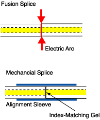
If you are installing an outside plant network such as a long distance network or a long campus LAN with splices between cables, you will want an OTDR to check if the fibres and splices are good. The OTDR can see the splice after it is made and confirm it’s performance. It can also find stress problems in the cables caused by improper handling during installation. If you are doing restoration after a cable cut, the OTDR will help find the location of cut and help confirm the quality of temporary and permanent splices to restore operation. On singlemode fibres where connector reflections are a concern, the OTDR will pinpoint bad connectors easily.

OTDRs should not be used to measure cable plant loss. That is the job of the source and power meter, which duplicates the actual fibre optic link, as we described in the first part of this article and is documented by every standard ever written for cable plant loss. The loss measured will not correlate between the two methods; the OTDR cannot show the actual cable plant loss that the system will see.

The limited distance resolution of the OTDR makes it very hard to use in a LAN or building environment, where cables are usually only a few hundred feet long. The OTDR has a great deal of difficulty resolving features in the short cables of a LAN and is more often than not simply confusing to the user.

And one OTDR manufacturer once told a class of students that they could justify the cost of an OTDR simply by using it to test the length of the fibre on a reel when they get it to make sure they got what they paid for. The class laughed at the instructor and pointed out the cable manufacturers mark length on the cable jacket and a £2 calculator would do as well!

Since OTDRs are very expensive and have only specific uses, the decision to buy one must be made carefully. For that reason, most instrument rental companies will rent one for a few days or weeks when you need them. However, if you are not familiar with their operation or cannot understand the results of OTDR tests, it would be much better to hire a specialist to do the testing for you.

How does an OTDR work?

OTDR

Unlike sources and power meters, which measure the loss of the fibre optic cable plant directly, the OTDR works indirectly. The source and meter duplicate the transmitter and receiver of the fibre optic transmission link, so the measurement correlates well with actual system loss. The OTDR, however, uses unique phenomena of fibre to imply loss.
The biggest factor in optical fibre loss is scattering. It is like billiard balls bouncing off each other, but occurs on an atomic level between photons (particles of light) and atoms or molecules. If you have ever noticed the beam of a flashlight shining through foggy or smokey air, you have seen scattering. Scattering is very sensitive to the colour of the light, so as the wavelength of the light gets longer, toward the red end of the spectrum, the scattering gets less. Very much less in fact, by a factor of the wavelength to the fourth power – that’s squared-squared. Double the wavelength and you cut the scattering by sixteen times!

Read more

Is OTDR testing necessary for premise cabling?

OTDRWhile there has been some “buzz” about Optical Time Domain Reflectometer(OTDR)testing for premises cabling since the publication of TSB-140, Additional Guidelines for Field-Testing Length, Loss and Polarity of Optical Fiber Cabling Systems, many agree that the test is usually not necessary for the relatively short links found in a customer-owned network, and may merely add unnecessary expense and complexity.

When testing an optical premises network, the key measurement criterion is insertion loss, or attenuation. This is effectively measured by using a power meter and light source. If the attenuation is within the limits of the allotted power budget, the system will work. OTDRs measure Raleigh backscatter, not absolute loss.

Supporters of OTDR testing in the premise environment believe that testing with an OTDR can help identify microbends that could potentially cause a problem; as well as help document the system for future verification. However, visual inspection is usually the best way to locate breaks or bends. While there may be some minor advantages in performing OTDR testing on premise cabling, the added cost usually outweighs the benefits.

What factors affect optical fiber splicing loss?

FS-60S Fusion SplicerThere are two types of factors that fiber splice loss depends on: intrinsic factors and extrinsic factors.

1、intrinsic factors
Mode Field Diameter Mismatch

Intrinsic factors are parameters that you can not control. These factors are determined when the fiber is manufactured and Mode Field Diameter (MFD) is the most critical one.

Differences in the mode field diameter between single mode fibers lead to a signal loss. More splice loss can be observed for higher difference in MFD values.
Read more

How to choose a best fiber optic power meter.

optical power meter
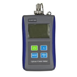
Fiber optic power meter measures how much light is coming out of a fiber optic cable; it can be used to determine the amount of light being generated by an optical source, or the amount of light being coupled into an optical receiver.

Optical power is usually measured in dBm, or decibels referenced to 1mW. These devices measure the average optical power, no the peak power, so they are sensitive to the duty cycle of the data transmitted. Their wavelength and power range have to be appropriately matched to the system being measured.

Most power meters used to best communication networks are designed to work at 850nm, 1300nm, and 1550nm wavelength ranges and in the power range of –15dBm to –35dBm for multimode links, or 0-40 dBm for single mode links.
Read more

Best Practices for Data Center Fiber-Optic Cabling Systems

images2Fiber-optic cabling is an ideal medium for data center networks, because of fiber’s ability to support high transmission speeds and long-distance connections. Many factors come into play when planning, deploying and administering a data center fiber-optic cabling system.
The following are some suggestions for efficient cabling and network management.

Presentation 1: Fiber-optic Port Replication—How and Why
Large volumes of connections in a densely packed environment are a hallmark of fiber-optic networks. In these connectivity environments, managing the large volume of fiber-optic cables can be a constant challenge. One means of easing and simplifying this management is to implement passive port replication. This presentation describes what port replication is, how it can be accomplished, and why it eases the cable-management burden for a data center administrator.

Presentation 2: Testing and Assuring Fiber Connections
Once a fiber-optic cabling infrastructure is installed to support data center networking, that infrastructure must be tested to ensure it performs at the expected performance level and supports the intended applications. This presentation discusses several critical aspects of fiber-optic testing, including proper reference setting, the role of encircled flux (EF) and its implications on test tools/procedures, as well as the ability to test different connector-endface types with a single test unit.

Presentation 3: Fiber Splicing in the Data Center
While preterminated systems have gained popularity for some data center settings and circumstances, many data center fiber-optic cabling systems can benefit from fusion-spliced connections. This presentation explains the circumstances under which splicing fiber represents an efficient and effective connectivity method. It describes the splicing technologies and techniques that can be put to effective use in data centers.